Thursday 13 September 2012

Programmable Robotic Platform

Many of beginners of robotics field feel that working with robots.If you are looking for a kick start robot kit here is the solution. recently Robogenisis released ATmega8 based development board in the market. which is very much compact in size and of affordable cost. with the help of this kit we developed a mini robot kit that is compatible with even Windows7  64 bit.

No special programmer is required as the board is self programmable.

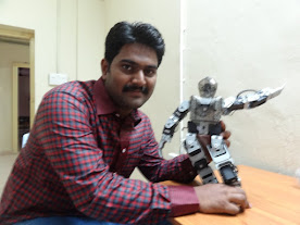
introducing the   V-2 Bot..............................................


you can just program the robot using USB cable
This robot was designed by considering students and hobbyists of beginners and medium. this development environment will help the user to reduce his//her efforts in making connections as all the peripherals are by default connected to the respective pins of the microcontroller. This circuit consumes less power so just two 9V batteries are required.here comes the BOT take a look at this
  

KIT CONTENT:

  1. ATmega8L development board.
  2. 16*2 alpha numeric LCD display
  3. Bread board for prototyping
  4. Power supply plugs
  5. Robot chases
  6. 100RPM DC geared motors
  7. 7cm plastic wheels with tires
  8. clamps and screws and screw driver
  9. USB cable
   
currently this kit is available in Hyderabad
for more details mail us at:

vaabrobotics@gmail.com

Thursday 2 August 2012

HC-SR04 ultrasonic sensor interfacing with 8051 microcontroller


If you want to make your robot sense the objects in it's surroundings i suggest you to go for an ULTRASONIC sensor.Though the IR based sensors are cheep, their working range may vary due change in ambient light and won't give accurate range values.
In case of ULTRASONIC sensors they work based on the principle of  RADAR(RAdio Detection And Ranging). A RADAR transmits electromagnetic "pulse" towards the target and receives the "echo" reflected by the target.

Then the range of the target is determined by the "time lagging" between transmitted pulse and the received "echo". Generally microwave and ultrasonic frequencies are used in RADARS
Our HC-SR04 ultrasonic sensor works similar to the  RADAR mechanism but in a simplified manner. This sensor consists of four PINS

1.Vcc------------------connect to 5V dc
2.Trigger--------------pulse input that triggers the sensor
3.Echo----------------indicates the reception of echo from the target
4.Gnd-----------------ground final

working with sensor step by step

                                Take a look at the timing diagram of HC-SR04 sensor
 
      This diagram describes the basic algorithm in distance measuring using the sensor.

 
STEP1.                                                                                                                                       Make "Trig" pin of the sensor high for 10µs. This initiates a sensor cycle. 
STEP2.                                                                                                                                              8 x 40 kHz pulses will be sent from the  transmitting piezzo transducer of the sensor, after which time the "Echo" pin on the sensor will go from low to high.
STEP3.                                                                                                                                               The 40 kHz sound wave will bounce off the nearest object and return to the sensor.
STEP4.                                                                                                                                       When the sensor detects the reflected sound wave, the Echo pin will go low again.
STEP5.  
     The distance between the sensor and the detected object can be calculated based on the length of time the Echo pin is high.
STEP6.                                                                                                                                     
        If no object is detected, the Echo pin will stay high for 38ms and then go low. 

configuring the 8051 microcontroller:

To inter face the sensor to AT89S51 microcontroller we need two I/O pins. One of them is external interrupt pin(INT0 or INT1) for measuring the pulse width at the echo pin. and  any other pin say P3.5 for trigger.

STEP1.                 Connect the trigger pin of sensor to P3.5 of AT89S51
STEP2.                 Connect the echo pin of the sensor to INT0 (P3.2) of AT89S51
STEP3.                 Configure the TIMER0 of 8051 in 16 bit mode with “GATE” bit enabled. If the GATE pin is enabled and timer run control bit TR0 is set, the TIMER0 will be controlled by INT0 pin. When INT0 is high then the TIMER0 starts counting. Whenever INT0 goes low TIMER0 holds its count. So load the TMOD register with 00001010==0x0A; (better refer to any book of 8051).
STEP4.                 As the INT0 pin is input don’t forget to declare the pin input. Write “1” to the pin to make it input.

algorithm

==>Send a 10 micro second high pulse at trigger
                                          Initially P3.5=0;
                                        P3.5=1;
                                       Delay(10 micro second);
                                         P3.5=0;
      ==>   "WAIT" until the sensor transmits the eight 40KHz pulses and signal reflection.
                            initially the "ECHO"pin is low when the transmitter completes the pulse the pin goes high then our TIMER0 starts counting.when input at INT0 goes low timer holds count.   logic for waiting:
                                while(INT0==0);
                                while(INT0==1); 
but some times due to errors in the sensor functioning the 8051 microcontroller may go into an "INFINITE LOOP" 
for that there are two remedies
1)use watch dog timer(present on AT89S52 and other advanced versions)
2)generate a delay of 40 milliseconds after triggering the ultrasonic sensor.
the second option is preferred for beginners.

      ==>TIMER0 value = time taken by the signal to (go forward+come back)
It meas the signal traces the whole distance twice. 
so time taken by the signal to travel the distance = TIMER0 value/2 
ULTRASONIC  pulse travels with the speed of sound 340.29 m/s = 34029 cm/s
range of target= velocity *time ==> 34029 * TIMER0/2
                                                  ==>  17015 * TIMER0
At 12MHz TIMER0 gets incremented for 1microsecond.
        RANGE    =    17015 centimeters/seconds  *  TIMER0 micro seconds

                           =    17015 centimeters/seconds *  TIMER0 * (10^-6)  seconds                 
                                     as            (1micro second=10^-6 seconds)
                        
                           =    17015 centimeters/secondsTIMER0 * (10^-6)  seconds 
                         
                             
                           =    17015  TIMER0     centimeters 
                                        (1000000)   
                           
                           =       TIMER0_______     centimeters 
                                    1000000/ 17015 

                           =       TIMER0_   centimeters 
                                    58.771

                   RANGE of target  =  TIMER0_   centimeters 
                                                            59
  
By using the formula we can calculate the range  of the target easily.

circuit diagram 

  CODE

      #include<REGX51.h>
#include<intrins.h>// for using
_nop_() function
        sfr16 DPTR =0x82;// you can use DPTR as a single 16 bit register
sbit trig=P3^5;
void send_pulse(void) //to generate 10 microseconds delay
{
TH0=0x00;TL0=0x00;
 trig=1;
 _nop_();_nop_();_nop_();_nop_();_nop_();
 _nop_();_nop_();_nop_();_nop_();_nop_();
 trig=0;
   
}

unsigned char get_range(void)
{
 unsigned char range;
 send_pulse();
    while(!INT0);//         in sake of these lines you can generate a delay of 40 Milli seconds=40000 micro
    while (INT0);//        
seconds
        DPH=TH0;DPL=TL0;
 TH0=0xFF;TL0=0xFF;
 if(DPTR<35000)//actually you need to use 38000 but the sensor may not work at higher levels
  range=DPTR/59;
  else
  range=0; // indicates that there is no obstacle in front of the sensor
  return range;
}
void main()
{//main begin
  TMOD=0x09;//timer0 in 16 bit mode with gate enable
  TR0=1;//timer0 run enabled
  TH0=0x00;TL0=0x00;
  P3|=0x04;//setting pin P3.2 to make it INPUT
          unsigned int target_range=0;
 while(1)
 {
    target_range=get_range();
        //make your own function to display the range value.better to use LCD
 }
}// end of main

Thursday 5 July 2012

ATmega8 based line follower robot

This project is a microcontroller based line follower robot by using ATmega8 development board from "ROBOGENISIS". This development board consists of an on board USB programmer, motor driver and some other peripherals like LEDs, buzzers. This board is best for beginners.This can be programed using WinAVR,programers notepad.


ATmega8 microcontroller consist 3 ports:
  •    PORTB an 8 bit I/O port
  •    PORTC a 7 bit I/O port .But pin PORTC.6 is also RESET pin for the MCU so it cannot be used for input but remaining 6 pins can be used as inputs.
  •    PORTD an 8 bit I/O port
  In this board the ATmega8 works at 12 MHz crystal.
An on board L293D is used for driving motors. Separate power supply is provided motor driver and logic supply for MCU. Motor driver control pins are internally connected to the higher nibble (D7, D6, D5, and D4) pins of PORTD.

To get familier with basics of line follower click here.

I connected the sensors to PORTC lower 2 pins left sensor to C1 & right one to C0. Connect two motors to the motor output ports.


 CODE:


#include<avr/io.h>
#define F_CPU 12000000
#include<util/delay.h>
void main()
{
  DDRC=0xc0;//input for sensors make sure that all sensors are active high
                                        //( high    for wight)
  PORTC=0xff;//internal pull up
  DDRD=0xff;//motor control pins
  PORTD=0x00;//motor halt
  unsigned char sensor;
 while(1)
 {
     sensor=PINC & 0x03;//masking for lower 2 bits
       if(sensor==0x03)// both are on white
   PORTD=0xaa;//forward
  else if(sensor==0x01)//left sensor on black line
   PORTD=0x66;//left turn
  else if(sensor==0x02)//right sensor on black line
   PORTD=0x99;//right turn
  else
   PORTD=0x00;//robot stop
  
 }
}


similarly for 8051 the code will be:


#include<reg51.h>

void main()
{
  P1=0xff;//input for sensors make sure that all sensors are active high ( high    for  Wight)
  //sensors are connected to lower two pins                                    
//in 8051 to make a port input you need to write one's to the respected pins
  unsigned char sensor;
//assume that motor control pins are connected to either upper or lower 4 bits of PORT2
 while(1)
 {
       sensor=P1&0x03;
       if(sensor==0x03)// both are on white
  P2=0xaa;//forward
  else if(sensor==0x01)//left sensor on black line
    P2 =0x66;//left turn
  else if(sensor==0x02)//right sensor on black line
    P2 =0x99;//right turn
  else
    P2 =0x00;//robot stop

 }
}


Wednesday 4 July 2012

TV remote controlled robot


The most cheapest way of controlling  the devises through wireless is IR remote.Every one in the world will have a TV remote which works based on RC5 protocol or some equivalent protocol.I searched over the internet for a perfect TV remote signal decoder compatible with all sensor like TSOP  and other cheep TV sensor.I all ways thought of making such TV remote signal decoder.

But recently i found a TV signal decoder in Hyderabad.compatible with all most all TV remotes except for DVD,AC remotes.Actually it is a handmade one.I found it in a hobby shop.I bought for 295 Rs. i made some modifications regarding the power supply for direct 5V Vcc to the decoder module.
This  one outputs a 5 bit address,6 bit data,a toggle bit and a valued data bit.
One important thing is the output form the decoder module will produce active low logic
if we press "2" on the remote the 6 bit data will be"111101"
if we press "4" on the remote the 6 bit data will be"111011"
if we press "0" on the remote the 6 bit data will be"111111"

I made a robot using that module.


I used a ATmega8 development board with ob board programmer for driving the motors as per the logic.
I removed the address pins on the decoder module and i connected the 6 bit address to the PORTC of ATmega8 and an L293D is used for driving motors which is internally connected to PORTD  higher nibble on the development board.

Tuesday 3 July 2012

home made 8051training board

Every beginner of microcontrollers all ways think of buying a prototyping board for practicing.Why don't you make your own board for working on your projects.I made a simple 8051 development board for prototyping my projects.You can make one by just spending less then 100 rupees.


For that you need very little equipment.
  • pin heads                                                                                                     
  • 40 pin IC base(i didn't get a 40 pin so i used a 42 pin) 
  • a 7805 voltage regulator
  • crystal (11.0592Mhz or 12.0Mhz as per your requirement)
  • 10kohm resistor
  • 10kohm resistor 9 pin array
  • 10uF electrolytic capacitor
  • 33pF disc capacitors
  • some connecting wires
  • a special PCB that consists of all row holes will be connected

PROCEDURE

first take a PCB with all its row holes connected as shown in the figure
 Cut the PCB as per the need of your size of board.First of all take a look at the pin diagram of AT89S52 microcontroller. The EA/VPP(pin 31) must be connected to VCC. The PORT0 must be pulled up through external pullups.So use the 9 pin 10K resistor array for pull up such that common pin to VCC and remaining 8 pins to PORT0 pins.
The power on reset circuit for 8051 will be as shown in the figure


 Connection of external ceramic crystal to the AT89S51

arrange all the components as shown in the figure below. step by step


cut the PCB like this

place the 40 pin IC base(i used 42 pin as 40 pin is out of stock)

take some pin heads
place them as per the port pins
and place the remaining required components like crystal,reset circuit,7805 voltage regulator for supply

your home made prototyping board for AT89S51.
for programing the  MCU you need a separate ISP programmer.
so many of them are available in the market. 
if you use P89V51RD2 microcontroller you just need a max232 IC and a serial cable to program it

Wednesday 13 June 2012

capacitor value identification

Identifying the capacitor value is a bit difficult compared to that of resistor.At the beginning i felt a lot of trouble.
first let us discuss the working of a capacitor.
INSIDE THE CAPACITOR
A simple capacitor consists of two parallel plates. When the two plates are connected to a dc voltage source (e.g., a battery), electrons are “pushed” onto one plate by the negative terminal of the battery, while electrons are “pulled” from the other plate by the positive terminal of the battery. If the charge difference between the two plates become excessively large, a spark may jump across the gap between them and discharge the capacitor. To increase the amount of charge that can be stored on the plates, a non-conducting dielectric material is placed between them. The dielectric acts as a “spark blocker” and consequently increases the charge capacity of the capacitor.Other factors that affect capacitance levels include the capacitor’s plate surface area and the distance between the parallel plates. Commercially, a capacitor’s dielectric may be either paper, plastic film, mica, glass, ceramic, or air, while the plates may be either aluminium disks, aluminium foil, or a thin film of metal applied to opposite sides of a solid dielectric. The conductor-dielectric-conductor sandwich may be left flat or rolled into a cylinder. The figure below shows some examples.


Here’s the best thing I could come up with in terms of a water analogy for a capacitor.  Pretend that electrons are water molecules and that voltage is water pressure. The water capacitor is built from two balloons. Normally, the two balloons are filled with the same amount of water; the pressure within each one is the same (analogous to an uncharged capacitor). In the figure, a real capacitor is charged by a battery, whereas the water capacitor is “charged” using a pump or pressurized water source. The real capacitor has a voltage across its plates, whereas in the water capacitor there is a difference in pressure between the two balloons. When the real capacitor is removed from the battery, it retains its charge; there is no conductive path through which charges can escape. If the water capacitor is removed from the pressurized water source—you have to pretend that corks are placed in its lead pipes—it too retains its stored-up pressure. When an alternating voltage is applied across a real capacitor, it appears as if an alternating current (displacement current) flows through the capacitor due to the changing magnetic fields. In the water capacitor, if an alternating pressure is applied across its lead tubes, one balloon will fill with water and push against the other semi filled balloon, causing water to flow out it. As the frequency of the applied pressure increases, the water capacitor resembles a rubber membrane that fluctuates very rapidly back and forth, making it appears as if it is a short circuit (at least in ac terms). In reality, this analogy is overly simplistic and does not address the subtleties involved in a real capacitor’s operation. Take this analogy lightheartedly.

KINDS OF CAPACITORS 

There are a number of different capacitor families available, each of which has defining characteristic features. Some families are good for storing large amounts of charge yet may have high leakage currents and bad tolerances. Other families may have great tolerances and low leakage currents but may not have the ability to store large amounts of charge. Some families are designed to handle high voltages yet may be bulky and expensive. Other families may not be able to handle high voltages but
may have good tolerances and good temperature performance. Some families may contain members that are polarized or nonpolarized in nature. Polarized capacitors, unlike nonpolarized capacitors, are specifically designed for use with dc fluctuating voltages (a nonpolarized capacitor can handle both dc and ac voltages). A polarized capacitor has a positive lead that must be placed at a higher potential in a circuit and has a negative lead that must be placed at a lower potential. Placing a polarized capacitor in the wrong direction may destroy it. (Polarized capacitors’ limitation to
use in dc fluctuating circuits is counterbalanced by extremely large capacitances.) Capacitors also come in fixed or variable forms. Variable capacitors have a knob that can be rotated to adjust the capacitance level. The symbols for fixed, polarized, and variable capacitors are shown below
CAPACITOR PACKAGES
 
These capacitors include both aluminum and tantalum electrolytic. They are manufactured by an electrochemical formation of an oxide film onto a metal (aluminum or tantalum) surface. The metal on which the oxide film is formed serves as the anode or positive terminal, the oxide film acts as the dielectric, and a conducting liquid or gel acts as the cathode or negative terminal. Tantalum electrolytic capacitors have larger capacitance per volume ratios when compared with aluminum electrolytic. A majority of electrolytic capacitors are polarized. Electrolytic capacitors, when compared with non electrolytic capacitors, typically have greater capacitances but have poor tolerances (as large as +_100 percent for aluminum and about +_5 to +_20 percent for tantalum), bad temperature stability, high leakage, and short lives. Capacitances range from about 1 μF to 1 F for aluminum and 0.001 to 1000 μF for tantalum, with maximum voltage ratings from 6 to 450 V.
This is very popular non polarized capacitor that is small and inexpensive but has poor temperature stability and poor accuracy. It contains a ceramic dielectric and a phenolic coating. It is often used for bypass and coupling applications. Tolerances range from +_5 to+ _100 percent, while capacitances range from 1 pF to 2.2 μF, with maximum voltages rating from 3 V to 6 kV.


This is a very popular nonpolarized capacitor that is reliable, inexpensive, and has low leakage current but poor temperature stability. Capacitances range from 0.001 to 10 μF, with voltages ratings from 50 to 600 V.


This is an extremely accurate device with very low leakage currents. It is constructed with alternate layers of metal foil and mica insulation, stacked and encapsulated. These capacitors have small capacitance and are often used in high-frequency circuits (e.g., RF circuits). They are very stable under variable voltage and temperature conditions. Tolerances range from +_0.25 to +_5 percent. Capacitance range from 1 pF to 0.01 μF, with maximum voltage ratings from 100 V to 2.5 KV


Variable capacitors are devices that can be made to change capacitance values with the twist of a knob. These devices come in either air-variable or trimmer forms. Air variable capacitors consist of two sets of aluminum plates (stator and rotor) that mesh together but do not touch. Rotating the rotor plates with respect to the stator varies the capacitor’s effective plate surface area, thus changing the capacitance. Air variable capacitors typically are mounted on panels and are used in frequently adjusted tuning applications (e.g., tuning communication receivers over a wide band

of frequencies). A trimmer capacitor is a smaller unit that is designed for infrequent fine-tuning adjustments (e.g., fine-tuning fixed-frequency communications receivers, crystal frequency adjustments, adjusting filter characteristics). Trimmers may use a mica, air, ceramic, or glass dielectric and may use either a pair of rotating plates or a compression-like mechanism that forces the plates closer together.


 Reading Capacitor Labels
Reading capacitor labels is tricky business. Each family of capacitors uses its own unique labeling system. Some systems are easy to understand, whereas others make use of misleading letters and symbols. The best way to figure out what a capacitor label means is to first figure out what family the capacitor belongs to. After that, try seeing if the capacitor label follows one of the conventions in the below figure


 Important Things to Know about Capacitors

Even though two capacitors may have the same capacitance values, they may have different voltage ratings. If a smaller-voltage capacitor is substituted in place of a higher-voltage capacitor, the voltage level across the replacement may “zap” its dielectric, turning it into a low-level resistor. Also remember that with polarized
capacitors, the positive lead must go to the more positive connection; otherwise, it may get zapped as well.
As a practical note, capacitor tolerances can be atrocious. For example, an aluminum electrolytic capacitor’s capacitance may be as much as 20 to 100 percent off the actual value. If an application specifies a low-tolerance capacitor, it is usually safe to substitute a near-value capacitor in place of the specified one.