

If you want to make your robot sense the objects in it's surroundings i suggest you to go for an ULTRASONIC sensor.Though the IR based sensors are cheep, their working range may vary due change in ambient light and won't give accurate range values.
In case of ULTRASONIC sensors they work based on the principle of RADAR(RAdio Detection And Ranging). A RADAR transmits electromagnetic "pulse" towards the target and receives the "echo" reflected by the target.


Then the range of the target is determined by the "time lagging" between transmitted pulse and the received "echo". Generally microwave and ultrasonic frequencies are used in RADARS
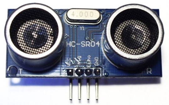
Our HC-SR04 ultrasonic sensor works similar to the RADAR mechanism but in a simplified manner. This sensor consists of four PINS
1.Vcc------------------connect to 5V dc
2.Trigger--------------pulse input that triggers the sensor
3.Echo----------------indicates the reception of echo from the target
4.Gnd-----------------ground final

working with sensor step by step
Take a look at the timing diagram of HC-SR04 sensor

This diagram describes the basic algorithm in distance measuring using the sensor.
initially the "ECHO"pin is low when the transmitter completes the pulse the pin goes high then our TIMER0 starts counting.when input at INT0 goes low timer holds count. logic for waiting:
while(INT0==0);
while(INT0==1);
but some times due to errors in the sensor functioning the 8051 microcontroller may go into an "INFINITE LOOP"
for that there are two remedies
1)use watch dog timer(present on AT89S52 and other advanced versions)
2)generate a delay of 40 milliseconds after triggering the ultrasonic sensor.
the second option is preferred for beginners.
==>TIMER0 value = time taken by the signal to (go forward+come back)
It meas the signal traces the whole distance twice.
so time taken by the signal to travel the distance = TIMER0 value/2
ULTRASONIC pulse travels with the speed of sound 340.29 m/s = 34029 cm/s
range of target= velocity *time ==> 34029 * TIMER0/2
==> 17015 * TIMER0
At 12MHz TIMER0 gets incremented for 1microsecond.
RANGE = 17015 centimeters/seconds * TIMER0 micro seconds
= 17015 centimeters/seconds * TIMER0 * (10^-6) seconds
as (1micro second=10^-6 seconds)
= 17015 centimeters/seconds * TIMER0 * (10^-6) seconds
= 17015 * TIMER0 centimeters
(1000000)
= TIMER0_______ centimeters
1000000/ 17015
= TIMER0_ centimeters
58.771
By using the formula we can calculate the range of the target easily.

STEP1.
Make
"Trig" pin of the sensor high for 10µs. This initiates a sensor cycle.
STEP2.
8 x 40 kHz pulses will be sent from
the transmitting piezzo transducer of the sensor, after which
time the "Echo" pin on the sensor will go from low to high.
STEP3.
The
40 kHz sound wave will bounce off the nearest object and return to the sensor.
STEP4.
When
the sensor detects the reflected sound wave, the Echo pin will go low again.
STEP5.
The distance between the sensor and the detected object can be calculated based on the length of time the Echo pin is high.
The distance between the sensor and the detected object can be calculated based on the length of time the Echo pin is high.
STEP6.
If no object is detected, the Echo pin will stay high for 38ms and then go low.
If no object is detected, the Echo pin will stay high for 38ms and then go low.
configuring the 8051 microcontroller:
To inter face the sensor to AT89S51 microcontroller we need two I/O pins. One of them is external interrupt pin(INT0 or INT1) for measuring the pulse width at the echo pin. and any other pin say P3.5 for trigger.
STEP1.
Connect the trigger pin of
sensor to P3.5 of AT89S51
STEP2.
Connect the echo pin of the
sensor to INT0 (P3.2) of AT89S51
STEP3.
Configure the TIMER0 of
8051 in 16 bit mode with “GATE” bit enabled. If the GATE pin is enabled and
timer run control bit TR0 is set, the TIMER0 will be controlled by INT0 pin.
When INT0 is high then the TIMER0 starts counting. Whenever INT0 goes low TIMER0
holds its count. So load the TMOD register with 00001010==0x0A; (better refer to
any book of 8051).
STEP4.
As the INT0 pin is input don’t
forget to declare the pin input. Write “1” to the pin to make it input.
algorithm
==>Send a 10 micro second high
pulse at trigger
Initially P3.5=0;
P3.5=1;
Delay(10 micro second);
P3.5=0;
==> "WAIT" until the sensor transmits the eight 40KHz pulses and signal reflection.initially the "ECHO"pin is low when the transmitter completes the pulse the pin goes high then our TIMER0 starts counting.when input at INT0 goes low timer holds count. logic for waiting:
while(INT0==0);
while(INT0==1);
but some times due to errors in the sensor functioning the 8051 microcontroller may go into an "INFINITE LOOP"
for that there are two remedies
1)use watch dog timer(present on AT89S52 and other advanced versions)
2)generate a delay of 40 milliseconds after triggering the ultrasonic sensor.
the second option is preferred for beginners.
==>TIMER0 value = time taken by the signal to (go forward+come back)
It meas the signal traces the whole distance twice.
so time taken by the signal to travel the distance = TIMER0 value/2
ULTRASONIC pulse travels with the speed of sound 340.29 m/s = 34029 cm/s
range of target= velocity *time ==> 34029 * TIMER0/2
==> 17015 * TIMER0
At 12MHz TIMER0 gets incremented for 1microsecond.
RANGE = 17015 centimeters/seconds * TIMER0 micro seconds
= 17015 centimeters/seconds * TIMER0 * (10^-6) seconds
as (1micro second=10^-6 seconds)
= 17015 centimeters/seconds * TIMER0 * (10^-6) seconds
= 17015 * TIMER0 centimeters
(1000000)
= TIMER0_______ centimeters
1000000/ 17015
= TIMER0_ centimeters
58.771
RANGE of target = TIMER0_ centimeters
59
By using the formula we can calculate the range of the target easily.
circuit diagram

CODE
#include<REGX51.h>
#include<intrins.h>// for using _nop_() function
sfr16 DPTR =0x82;// you can use DPTR as a single 16 bit register
sbit trig=P3^5;
void send_pulse(void) //to generate 10 microseconds delay
{
TH0=0x00;TL0=0x00;
trig=1;
_nop_();_nop_();_nop_();_nop_();_nop_();
_nop_();_nop_();_nop_();_nop_();_nop_();
trig=0;
}
unsigned char get_range(void)
{
unsigned char range;
send_pulse();
while(!INT0);// in sake of these lines you can generate a delay of 40 Milli seconds=40000 micro
while (INT0);// seconds
DPH=TH0;DPL=TL0;
TH0=0xFF;TL0=0xFF;
if(DPTR<35000)//actually you need to use 38000 but the sensor may not work at higher levels
range=DPTR/59;
else
range=0; // indicates that there is no obstacle in front of the sensor
return range;
}
void main()
{//main begin
TMOD=0x09;//timer0 in 16 bit mode with gate enable
TR0=1;//timer0 run enabled
TH0=0x00;TL0=0x00;
P3|=0x04;//setting pin P3.2 to make it INPUT
unsigned int target_range=0;
while(1)
{ target_range=get_range();
//make your own function to display the range value.better to use LCD
}
}// end of main
while(1)
{ target_range=get_range();
//make your own function to display the range value.better to use LCD
}
}// end of main
